MULTISIM - HALF WAVE & FULL WAVE RECTIFICATION
Rectification:
Rectification systems are primarily designed for converting sinusoidal AC input signals into a DC voltage signals. They are most commonly used in domestic power supplies and power transmission systems. Single wave rectification can be achieved by using either a half wave or full wave rectification circuit.
1. Half Wave Rectifier
Half-wave rectification systems utilise a single diode, removing half of the sinusoidal source. This produces a single directional signal with a pulsating characteristic.
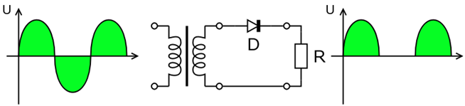
As a result of the heavy pulsating nature of the signal, more filtering is required to eliminate any harmonies from the AC source and provide a constant DC signal. The efficiency of the half wave rectifier is also limited because only half the sinusoidal waveform is being converted to the DC signal. Losing this half of the signal can be comparable to losing energy.
Circuit Diagram:

Wave Form:

2. Full Wave Rectifier
Full-wave (full bridge) rectifiers construct a bridge of diodes to convert the whole of the input voltage to one of constant polarity. This is more efficient than the half wave rectifier as it allows both the positive and negative components of the input voltage to be utilised in building the DC voltage.

Once the signal has a single polarity we can apply a simple filter to provide a DC voltage source. This filter applies a smoothing effect allowing the DC output to be maintained.
Circuit Diagram:

Waveform:


Comments
Post a Comment